Theory
In order to estimate position, various tracking technologies are based on observations of various phenomena. Outputs from different sensors are given in units as part of a particular coordinate system, defined within a particular frame of reference. A reference frame is specified by an ordered set of three mutually orthogonal, unit length direction vectors with an associated centre. A coordinate system specifies a mechanism for locating points within a reference frame. In order to use different measurements to abstract positional information, knowledge of both the coordinate systems and frames of reference employed is required.
Frames of Reference
A frame of reference may be inertial or non-inertial, body-fixed or environment-fixed. An inertial frame of reference can be stationary or moving at constant velocity, and therefore is not subject to acceleration. Objects considered within this frame of reference obey the law of inertia, as opposed to those within a non-inertial frame of reference. Body-fixed frames are tied to the body under test and rotate with it, while environment-fixed frames are independent of the moving body.
Earth-Centred Earth Fixed Frame
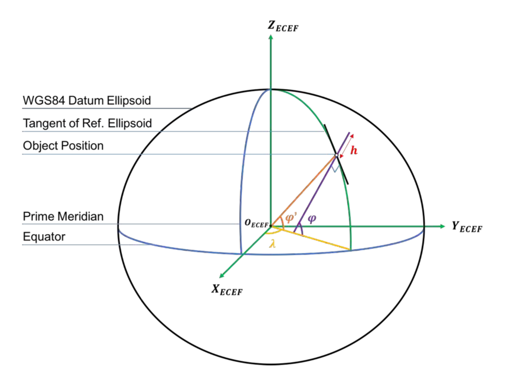
The Earth-Centred Earth-Fixed (ECEF) frame of reference is used as an environment- fixed frame for observations of position, velocity and acceleration of objects on earth. It is defined by the origin, OECEF which is located at the center of the earth and three axes which are fixed with respect to the surface of the earth, and thus constantly rotating with the planet. The Z-axis, ZECEF, extends from the origin towards the true north, or along the direction of the geographic North Pole. The X-axis, XECEF, extends from the origin along the direction of the point on the sphere of the earth at 0° latitude and 0° longitude. The Y-axis, YECEF, is the axis orthogonal to the Z and X axes using the right-hand rule. These are shown in the Figure 1.
Body Frame
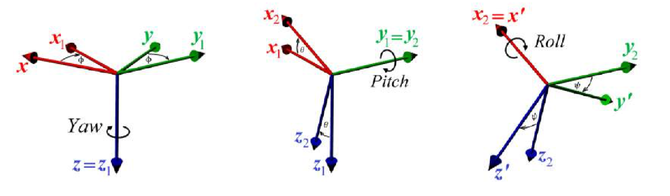
For a particular object, the body frame is defined by the origin at its centre of mass, and the coordinate axes aligned along the principal directions of the body. This frame moves freely within an environment-fixed frame such as the ECEF, and is typically used to express the rotations of a rigid body. For terrestrial objects, The rotation of a rigid body’s frame is described by Euler angles, conventionally using the yaw, pitch and roll convention denoted as φ, θ and ψ respectively. This is illustrated in Figure 2.
Coordinate Systems
Geodetic Coordinate System
Different coordinate systems can be used to refer to the same point within a reference frame. The geodetic coordinate system is used to define a point close to the Earth’s surface in terms of latitude, longitude and altitude, denoted as φ, λ and h respectively. A particular point is defined by the measurement of each parameter with respect to a corresponding datum. The latitude is an angular measurement which specifies the position north or south of the Earth’s equator. It ranges from 0° at the Equator to 90° North or −90° South at the poles. GNSS receivers output the position in terms of the geodetic latitude, φ, rather than the geocentric latitude, °′, which is defined as the acute angle between the equator and a line drawn perpendicular to the tangent of the reference ellipsoid. The longitude, λ is an angular measurement which specifies the position east or west of the Prime Meridian, varying from −180° to the west and 180° to the east. In geodesy, earth is approximated as an oblate ellipsoid, and the reference ellipsoid used for the GPS is defined by the World Geodetic System 1984 (WGS84) datum. The altitude is the local vertical distance between the measured point and the reference ellipsoid. These parameters are illustrated in Figure 1.
Earth-Centred Earth-Fixed Coordinate System
The ECEF coordinate system is a Cartesian system by which any point on the earth’s surface can be defined. The coordinate system is defined within the ECEF frame of reference, using the same origin and axes, shown in Figure 1.
Local North-East-Down Coordinate System
The local North East Down (NED) Coordinate System is a coordinate frame fixed to the earth’s surface. The origin is fixed to an arbitrary point on the earth’s surface. The X-axis points toward the WGS84 ellipsoid north, the Y-axis points toward the ellipsoid east, the Z-axis points downwards along the ellipsoid normal.
Conversions
In order to simplify algorithms, it is convenient to convert observations obtained within different frames of reference using different coordinate systems into a single system.
Geodetic to Local NED Coordinates
In order to transform from the geodetic system to the local NED system, coordinates are transformed to the ECEF system as an intermediate step. The conversion uses parameters from the WGS84 model:
- REa = 6,378,137.0m, the semi-major axis
- REb = 6,356,752.314m, the semi-minor axis
In an ellipsoid, the physical radius is not the same as the radius of curvature. For a specific latitude, φ, the radii of the spheroid ME and NE are obtained from the WGS84 model.
- ME: the radius used for changing the latitude to North distance, called the meridian radius of curvature.
- NE: the radius used for longitude, called the prime vertical radius of curvature given by Equation (2).
For a point defined in the geodetic system by the coordinates φ, λ and h, the coordinates of the same point in the ECEF system, xe, ye and ze are given by the standard transformation in Equation (3).
\begin{equation} \tag{3} P_e = \left(\begin{array}{c} x_e \\ y_e \\ z_e \\ \end{array}\right)\\ = \left(\begin{array}{c} \left( N_E + h\right) \cos{\varphi} \cos{\lambda} \\ \left( N_E + h\right) \cos{\varphi} \sin{\lambda} \\ \left[ N_E \left( 1-e^2 \right) + h \right] \sin{\varphi} \\ \end{array}\right) \end{equation}The local NED system defines a point with respect to some origin, which needs to be defined in ECEF coordinates, Pe,ref, and geodetic coordinates, φref, λref and href. A standard rotation matrix, Rn/e, which transforms the points from the ECEF frame to the local NED frame is given in Equation (4).
\begin{equation} \tag{4} R_{n/e} = \left(\begin{array}{ccc} -\sin{\varphi_{ref}}\cos{\lambda_{ref}} & -\sin{\varphi_{ref}\sin{\lambda_{ref}}} & \cos{\varphi_{ref}} \\ -\sin{\lambda_{ref}} & \cos{\lambda_{ref}} & 0 \\ -\cos{\varphi_{ref}}\cos{\lambda_{ref}} & -\cos{\varphi_{ref}}\sin{\lambda_{ref}} & -\sin{\varphi_{ref}} \\ \end{array}\right) \end{equation}The local NED coordinates, xn, yn and zn are obtained using Equation (5).
\begin{equation} \tag{5} P_n = \left(\begin{array}{c} x_n \\ y_n \\ z_n \\ \end{array}\right) = R_{n/e}\left(P_e - P_{e,ref}\right) \end{equation}Local NED to Geodetic Coordinates
In order to transform from the local NED system back to the geodetic coordinate system required for plotting on a map, the coordinates were again converted to the ECEF system as an intermediate step using the same parameters from the previous section. By rearranging Equation (5), and considering that the rotation matrix, Rn/e, is an orthogonal matrix, the ECEF coordinates, xe, ye and ze were obtained using Equation (6).
\begin{equation} \tag{6} P_{e} = \left(\begin{array}{c} x_e \\ y_e \\ z_e \\ \end{array}\right) = {R_{n/e}}^T P_n + P_{e,ref} \end{equation}While any point on earth may only be defined using a set of unique points in the ECEF coordinate system, this is not true for the geodetic coordinate system. In fact, for the points at the poles of the earth, located at a latitude of ±90°, the longitude can be defined as any degree value. Due to this problem, while the conversion from geodetic to ECEF may be performed using standard equations (Equation (3)), a more complicated method is required for the inverse. In order to obtain the equivalent geodetic coordinates from the ECEF system, a standard iterative method which performs operations until the results converge was implemented. This algorithm is illustrated in the flowchart shown in Figure 3.
